| Home | Empennage | Wings | Fuselage | Controls | Canopy | FWF | Panel |
|
|
Canopy Last Update: June 24, 2011 |
Making the Team Rocket (F1) Sliding Canopy Fit the HR-II
The HR-II is narrower at the rear seat back bulkhead position, and some of the cockpit details are different. This complicates the fit-up of the Team Rocket sliding canopy. In the end, with a couple of key modifications, everything comes together properly. Mark Frederick at Team Rocket sent me all the bits I need for the Slider Canopy. This includes the seat back brace, the gusset plates (pic below) roll bar, slider canopy frame and bubble windscreen (if required) and all of the required hardware. To ship the canopy to me, Mark cut off the front of the bubble to reduce its size. I am using the speed-slope windshield so the bubble front is not required.
Most importantly, he gave me access to all of the Team Rocket assembly instructions, which I downloaded and have on my workshop computer.
Step 1: Installing the seat back weldment.
Tip: Positioned the seat back brace and associated gussets in the position indicated in the Team Rocket instructions. Kept the top of the brace at the indicated position and tilted the weldment to fit in position. This may look wrong, but if you just line it up to the gusset, you won't have a lot of room to slide into the pilot's seat! Don't get the brace too high or it will interfere with the roller trucks later on.
This is complicated by the differences between the HR-II and F1 Rocket at this position, but you can see from the photo that it can be made to fit.

After tack welding the seat back with my cheapo MAPP-OXY torch, I brazed up a jig and took the assembly to the welding shop for finish welding. Later on, I had it sandblasted and powder coated.

Since I had to remove for finish welding, I brazed up a jig to hold everything in position. Worked fine.

Step 2: Attach the roll bar (AKA Windshield Bow)
No suprises here, just follow the TR instructions.
Step 3: Fitting the glareshield skins.
A lot of forming over a 3" drain pipe, plus shrinking the inflection point. It would have been easier with Alclad, but the stuff Mark Frederick sent me was bare 2024-T3 which is tougher to form.

Here's the inflection point where the shrinker came in handy.


Step 4: Canopy Track Installation.
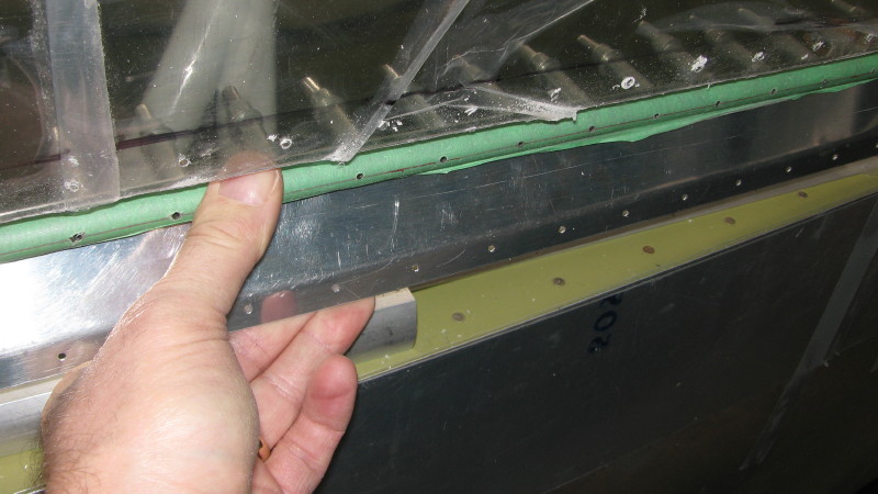
Tip: Roller trucks extended 3/8" to allow front tracks to be placed further outboard (HR-II is a bit different than the F1 Rocket in this respect because the HR-II is a bit narrower at the rear seat bulkhead)
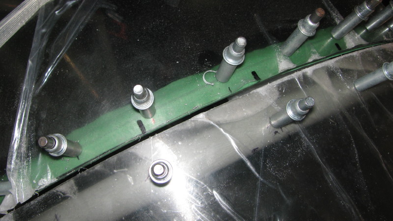
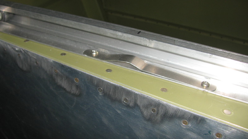
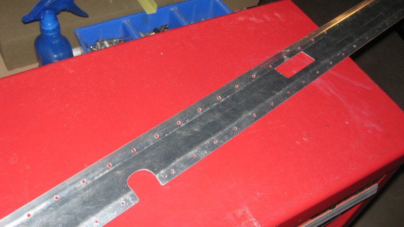
I used washers, but I will probably fabricate an aluminum spacer for final fit-up. The notch in the slider track is from a previous attempt at track installation before I determined that the front tracks needed to be moved outboard for proper canopy fit. Ditto the spare hole which will be filled with JB-Weld.

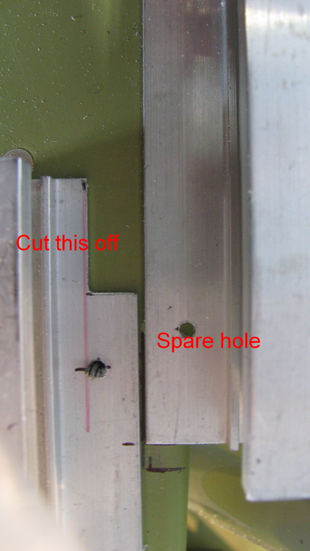
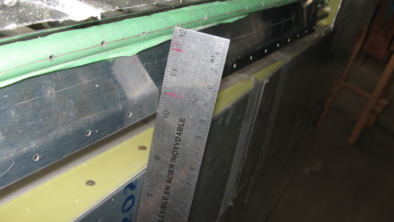
Here's the fit of the forward tracks and forward bow. The tracks are as far outboard as they can be placed, consistent with being parallel to the rear tracks. Not shown in this photo is the spacer (stack of washers) that is shown above.

Step 5: BowFlex and SpineTrak (good name for exercise equipment)
Fitting the forward and aft bows. The aft bow was cut down about 1" each side to fit the narrower HR-II fuse. This also cuts off the pins, which were welded back on later. The spine track was rebent to allow more adjustment range to set the height of the modified aft bow. Just clamped it in the soft jaws of my vice and gave it a gentle bend further upstream, and bit of a straighten downstream.
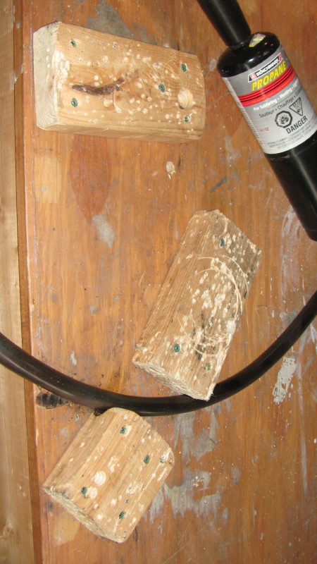
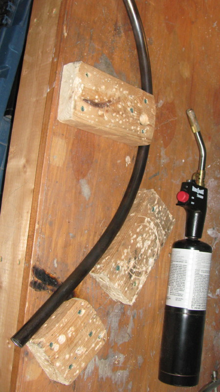
Bending the bows was easy by using softwood blocks screwed to my workbench and a good-quality propane torch. Heated the outside of any bend area to a dull cherry red to make the bends. Softwood tends to crush, forming a semicircular profile that is ideal for bending the steel tubing.
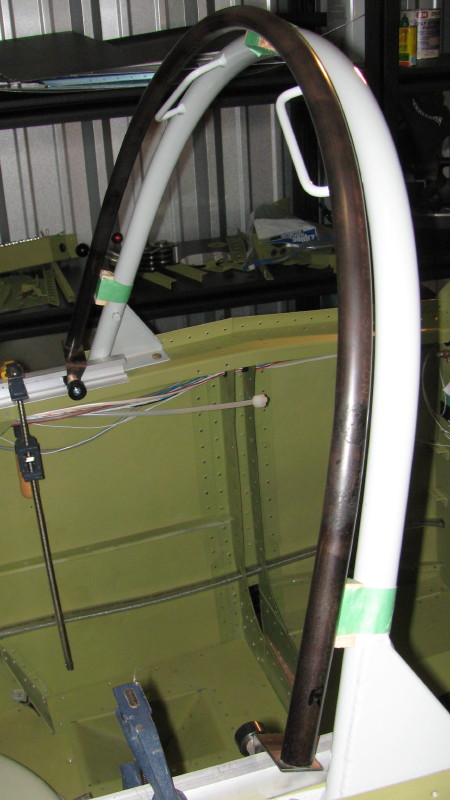
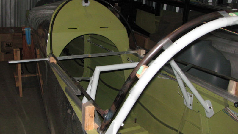
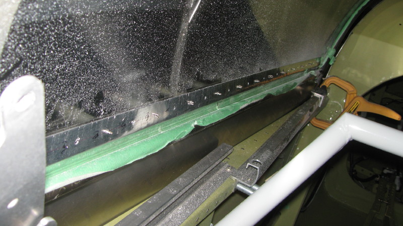
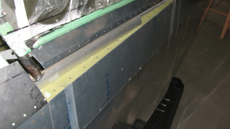
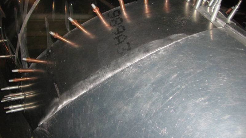
A shot down the fuse showing the fit of the forward and aft bows. Sighting down the fuselage this way gives a good indication of what needs to be done to get a good fit. Two things about this pic. First, you can see that the left side (right side in pic) is a little higher than the other side. Also, the forward bow is not high enough. This is not obvious, but it's my fault for cutting 1/8" off of each end of the forward bow to get the 3/8" step called for in the instructions. Don't do this! Wait until you mount the canopy and windscreen to make final height adjustments. Just get the shape even and matching left to right.

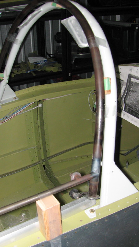
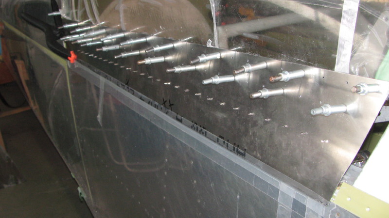
A shot up the fuse to see the fit of the aft bow. White dust from trimming the windscreen is everywhere. Again, this kind of sighting gives immediate feedback on bending progress.

Another shot of the forward bow. You can see my instrument panel here. I can't afford color EFIS systems, so the black and whites will have to do.

Forward and aft bows tack welded in place.

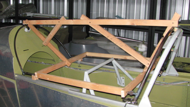
The entire frame tack welded, ready to be jigged for removal.
The canopy jig is almost complete. Strapping will be screwed on to hold the bows tight to the jig where they are notched. Notches were made from 1/2" (or 3/4") holes opened up to slide onto the bows. Since my tack welds are fragile, this will help keep everything together during finish welding.
Step 6: Fitting the Speed Slope Windshield
Follow the TR instructions
Step 7: Fitting the Canopy Bubble
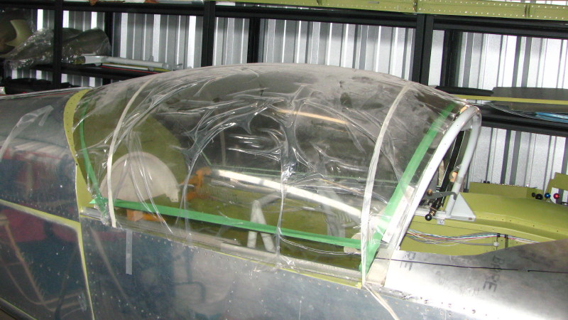
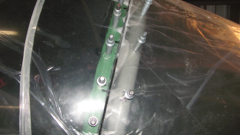
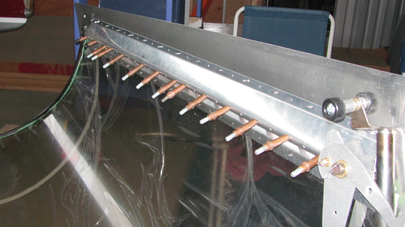
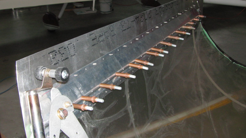
The slider frame is set to position using 9/16 spacer blocks between the windshield bow and the front canopy bow (3 places). The aft bow height is set by sliding the track fore and aft until a straight edge laying on the spine track is tangent to the canopy right over the aft bow. The pin locks are clamped in place and the canopy is placed over the frame. Several cuts are made to get it to about the right fit, with material to spare. This picture shows the front and back edges trimmed, but not the sides yet.
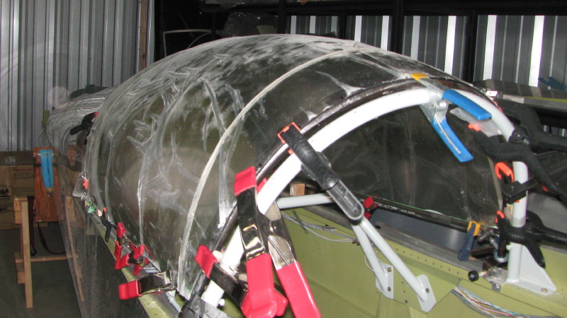
After much trimming and checking with the windscreen in place (not shown), the canopy is near it's final shape. It's time to do a final check of the fit, so everything is clamped down. Then the forward bow clamps are removed and the windscreen is clecoed into place for a fit check.
Hmmm. Looks like the canopy is about 1/8" too low! Drat... I had cut about 1/8" off of the bow ends to meet the 3/8" spec provided. Turns out I should have waited.
Nevertheless, I shimmed the roller trucks up 1/8" and adjusted the curve of the bow a bit by heating with my MAPP torch and bending using my workbench jigs. I had to drill new holes to pin the trucks to the bow. Everything looked good, so I started drilling and clecoing. With masking tape on the bows, pressure from the plexi causes a dark line to appear at the tangent point... that's the line to drill on. Drilled every 2", but left the bottom holes undrilled, just in case.
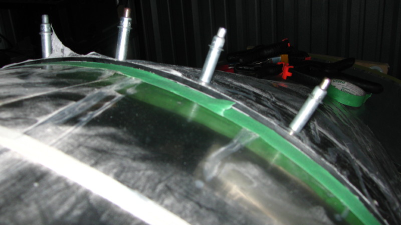
The result: about a 1/32" maximum offset between the windscreen and canopy plexi. Can't see it in these pics, which shows the specified 1/8" longitudinal gap between the two. Two things that do not fit properly are the canopy latches, which are too long. I make cut and splice them or fabricate new ones to work properly. Update: By making the gap a little bigger, the latches will fit unmodified. The gap will be hidden with a fiberglass fairing later on, so this is of no consequence.
Step 8: Fitting the Canopy Side Skirts
The instructions are a bit hazy, but I started by trimming the side skin, C-059 and UHMW strip to match the angle of the bottom front of the canopy, so they are a linear extension of the canopy shape. The C-059 and UHMW strip are set in about 1-1/8" +/- to match the overlap of the canopy from the front bow. These two parts sit behind the front bow, with about 1/8" clearance. The picture is deceptive, the outside skin is actually tapered. This is the setup for the right side.

The side skirts fit pretty well with some minor bending over a 2" poly pipe. Most of the bending was along the forward part. First, I used a 3/4" edge roller to bend the top of the skirt slightly outward-- more so in the forward area rather than than aft area where the skin is relatively straight.
The forward skin is bent inwards slightly, then outwards near the bottom, forming a bit of a shallow "S" curve. With the windscreen in place, this lined up very well. Things fit pretty well along the side, with some minor tweaking. The skins actually fit reasonably tight to the side skins, which is better than too loose. Later, I will line the inside of the slider with a felt rub strip, which works really well to help seal the canopy and prevent abrasions on the paint.

The C-509 strips that capture the canopy need quite a bit of flange bending to follow the bubble. I used a large crescent wrench to bend the flanges so that sat flush with the bubble. Once set, I drilled through the side skirt, bubble and C-509, lining up with the existing holes.
The C-059B skirt brace also need some bending to follow the side skirts closely. In order to do this, I did a rough bend to get close, drilled the strips along the side bow, then clecoed them in place. Using my fingers (two hands), I then bent out the bottom flange to follow the side skirts. Since the skirts are not in place when I did this, I just lined up the C-059B flange with the fuselage skin for most of the distance. The forward portion is a bit more inboard.
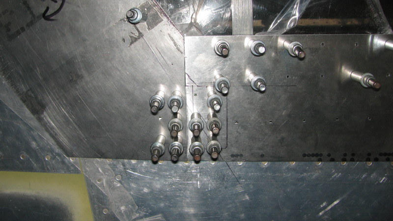
Once this bending was done, the C-059B put a slight even pressure on the side skins, allowing the canopy assembly to be clecoed together and the side skirts taped down to the fuselage sides. I taped an 0.025 shim onto the sides of the fuselage so that the side skirt would be held proud of the fuselage during drilling the C-059B. Since the side skins were already tight to the skin, the idea here was to help relieve the pressure and prevent paint abrasion later on. The picture below has the strip in place, plus a strip of tape holding the side skirt down.
I then crawled into the fuselage, drilled the C-059B to the side bows up to #30 and drilled the C-059B to side skirt holes, which were pre-drilled on the bench for the skirt attach holes. I clecoed everything together from the inside as I went , then later transferred the clecoes to the exterior.
Step 8: Fitting the Canopy AFT Skirts
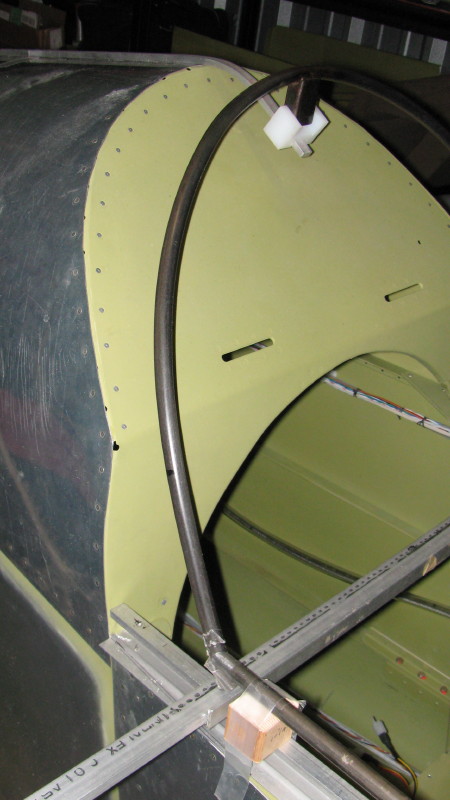
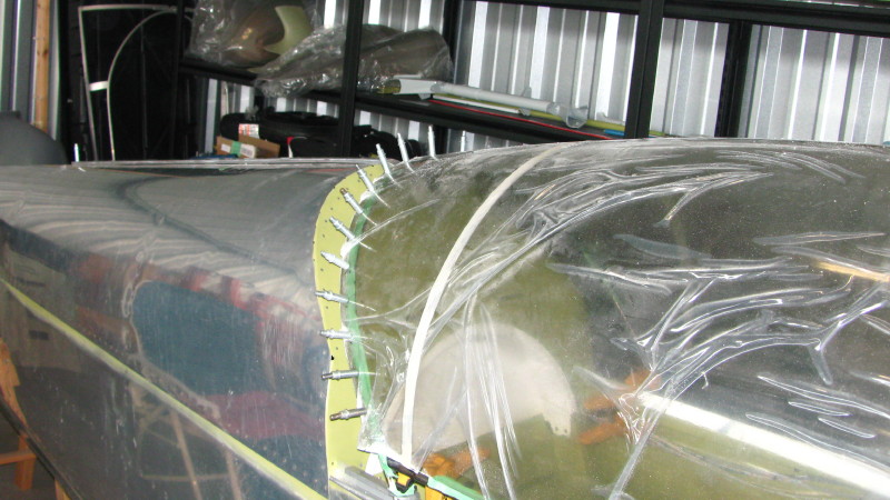
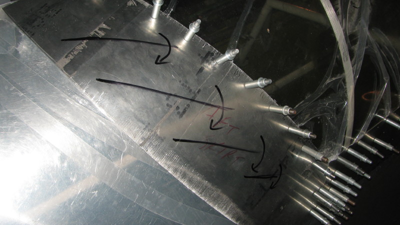
The key to fitting the aft skirts is to roll the skins into a spiral, primarily in the region and on the angle indicated in the picture. I used a 2" plastic drain pipe for this, but a slip roller would work really well. Keep rolling until the skin fits as close as possible. Fine tune the curl as required with a shrinker along the edges. The first one took about 4 hours to fit and drill. The second one took about 20 minutes to fit, not including the drilling.
A key to getting the aft part of the skirt to pull down to the fuselage is tension. The TR instructions say to offset the top two and bottom two holes in the skirt by half a hole width to increase this tension. When I taped everything down prior to drilling, most of the tape was used to pull the skirt into tension. You can see some of the transparent tape in the picture below. This is hockey sock tape-- tough and stretchy. The doubler required to connect the aft skirt to the side skirts shown in the TR plans only has two rivets each side. I have 6 rivets because this area is under a lot of tension and open and closing the skin will work the rivets. I'll rivet the doubler to the side skin before assembly so the latch pin won't interfere with riveting.
Step 9: Details
Canopy Latches: No doubt because of the dimensional differences of the HR-II vs. F1 Rocket, the latch hooks were slightly too long. No problem, I made new hooks and riveted them in place. Both sides needed adjustment.

Canopy Stop: I had purchased a fancy sliding canopy from Vince Frazier (Flyboy Accessories), shown below. It wouldn't fit on the Rocket, so I developed an alternative.

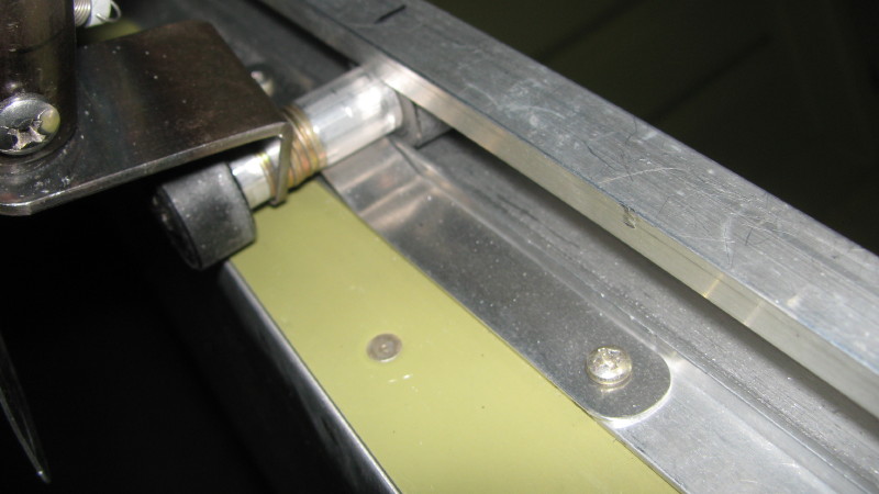
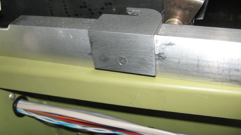
Here it is. Cost, nil. Weight, nil. Time to make, virtually nil. Effectiveness, priceless! This strip of 0.032 Aluminum provides a ramp that will stop the canopy from sliding all the way back unless pushed firmly past. You'll notice the ramp is asymmetrical... less resistance sliding forward than sliding aft.
It's adjusted by changing the bend angles until the right amount of resistance is encountered. If it ever wears out, it can be replaced. Even a piece of stainless would work well here. It is mounted using existing slider track screws.

Here's how well it works:
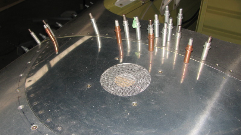
Defogging Fan. I used a 92 mm computer muffin fan and stainless screen as a defogging/avionics cooling fan. The hole was cut with a 3-1/8 instrument panel punch, which is perfect. Both the fan and the screen were procured from Digikey when I was building my 9A. I ended up using only one on the 9A, so I finally go to use the spare.
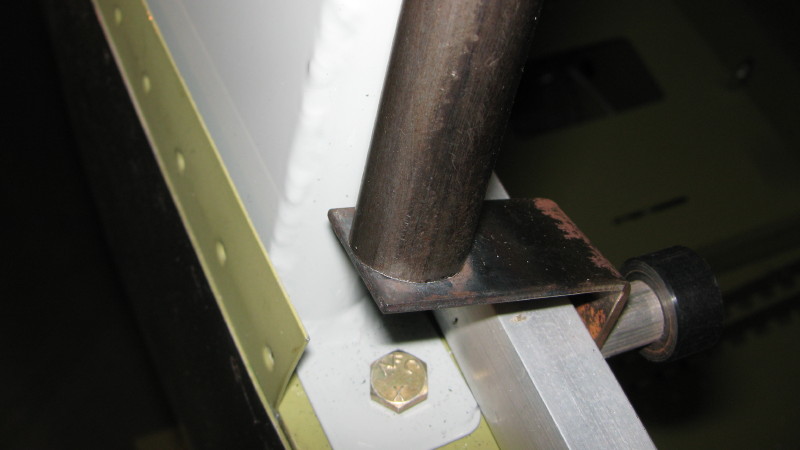
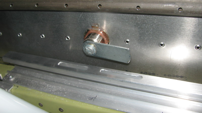
As a canopy latch retainer I settled on tapping the steel nipple 7/16 and using a 1" x 7/16" bolt, shortened to 1/2" using my die grinder. The large fender washer is 1/2" in diameter and slides over the nipple to retain the brass bushing without any bearing force from the bolt. This means trimming the nipple 1/16" longer than flush. I had originally used 4-40 set screws in the brass bushing, but with all of the abuse these latches get, I think the bolts are a better way to go.


Lock: The lock matches the key from my 9A, so I wanted to reuse it for the Rocket. Two locks came with an ACS ignition switch. The forward (right) slot is for locking the canopy in the fully closed position. The aft (left) slot is for locking the canopy in a slightly open position to allow for ventilation on hot days. I found that the cam on the lock was too short to reach the aft slot because the canopy lifts up when it is slid back. I purchased another lock from the canopy latch aisle at the local hardware store and used it's longer cam. I shortened it to fit just right. The lock is centered on one of the rivet hole locations.
The horseshoe cutout in the C-059B is for the lockset.
Canopy Hold-Down Fixtures. These were riveted to the tracks using AN426AD4 rivets. Mash the tails properly to clear the roller track. These will take a lot of abuse, so I used 3 rivets each side. I also shaped the hooks to guide the pins in smoothly.
Glam Shots: Here's the fit for the right aft shirt. The swirls are from a rotary scotchbrite wheel run over the shrink marks.

And here's the left aft skirt.
Doghouse: The doghouse will mount to the exterior so the skirt fits flush. The splice plate mounts underneath in final assembly.

Same with the side skirt splice plates.

Well, that's a wrap on the canopy pre-fit. All of the holes are drilled and tapped as required and the funky rubber grommets made from rubber hose are in place on the windshield. Everything is ready to prep for primer and paint. In final assembly, I'll be using some caulking to stress relieve the plexi attachment wherever there are screws or rivets through the plexi. I still haven't attached the funky yellow balls to the latch handles, as I have to order them from Van's. I won't be doing the aft handles because they would only ever be used in an emergency and the stock handles are fine.
