| Home | Empennage | Wings | Fuselage | Controls | Canopy | FWF | Panel |
|
|
EMPENNAGE Last Update: June 24, 2011 |
HS Stabilizer Reinforcement
Based on recommendations from Mark Frederick at Team Rocket (designer of the F1 Rocket), the RV-4 HS should be reinforced. Already, the HS is using 0.032 skins, but there has been reports of tail shake at high speed. The fix appears to be adding 6 stiffeners per side (3 top, 3 bottom), fabricated out of 0.032 or 0.040 T2024-T3.
An additional 0.040 T2024-T3 forward spar reinforcement is suggested (but not recommended), approx 32-36" long as a doubler on the front spar between the left and right sections.
Since my HS had not been closed out, awaiting MD-RA inspection, it was easy to drill out a few lines of rivets and roll the skins up. I also removed the root ribs for access.
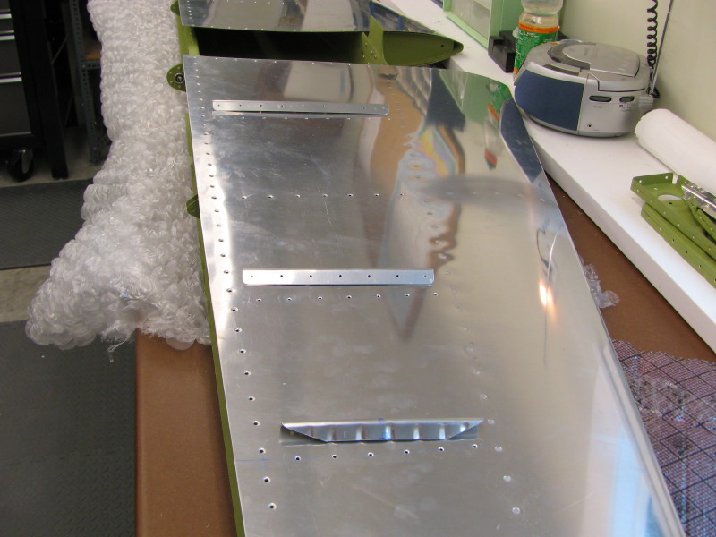
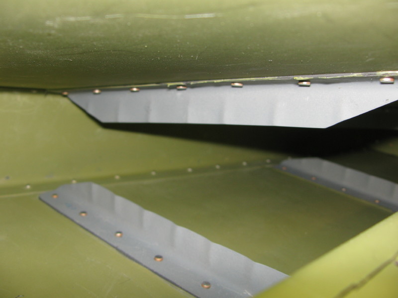
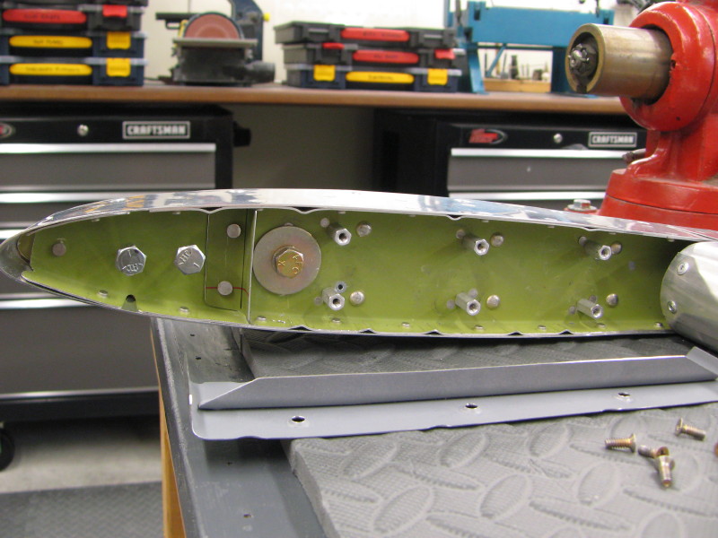
This photo shows the completed 0.032 stiffeners, fluted to fit the shape of the skin. The HS skin is countersunk for NAS1097AD3-4 rivets (small head rivets) and the ribs will be Prosealed in place, with the rivets as a secondary attachment. Using the NAS rivets allows countersinking. If the skins were not attached, everything could have been dimpled and MS rivets used, with no Proseal.
HS Stiffeners
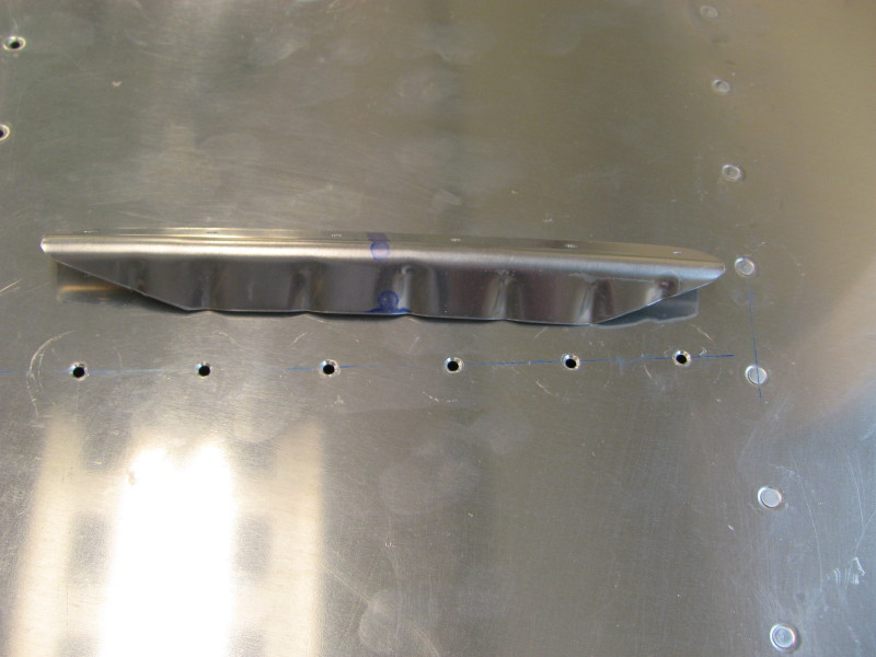
HS Stiffener Closeup
Forming the HS Stiffeners
Non-Reinforced HS Forward Spar
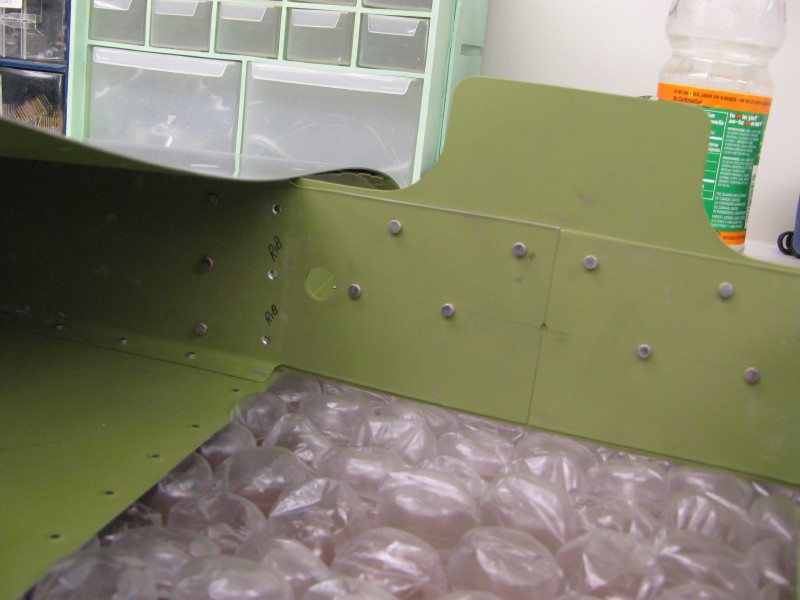
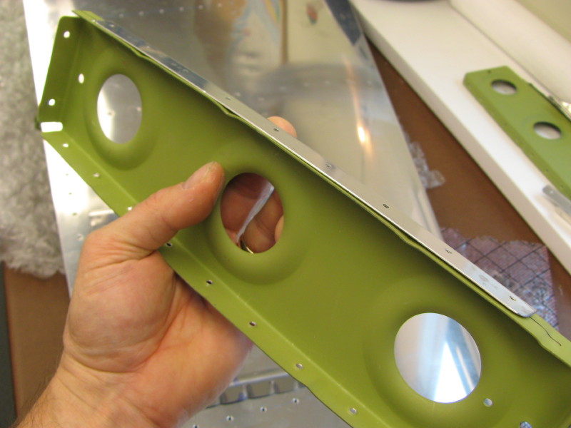
Reinforced HS Spar (center), with Rib flange modification
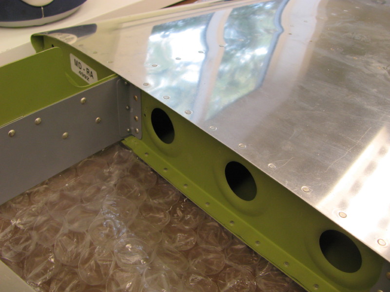
Reinforced HS Spar (right)
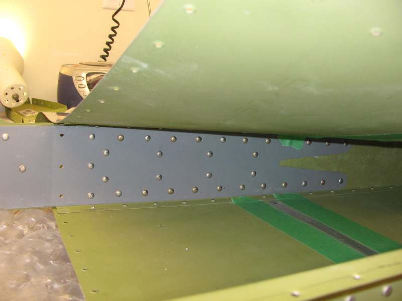
Reinforced HS Spar (left).
Note detail of stiffener attachment. Aluminum is roughed up and masked prior to Proseal & NAS1097 rivet attachment of stiffener.
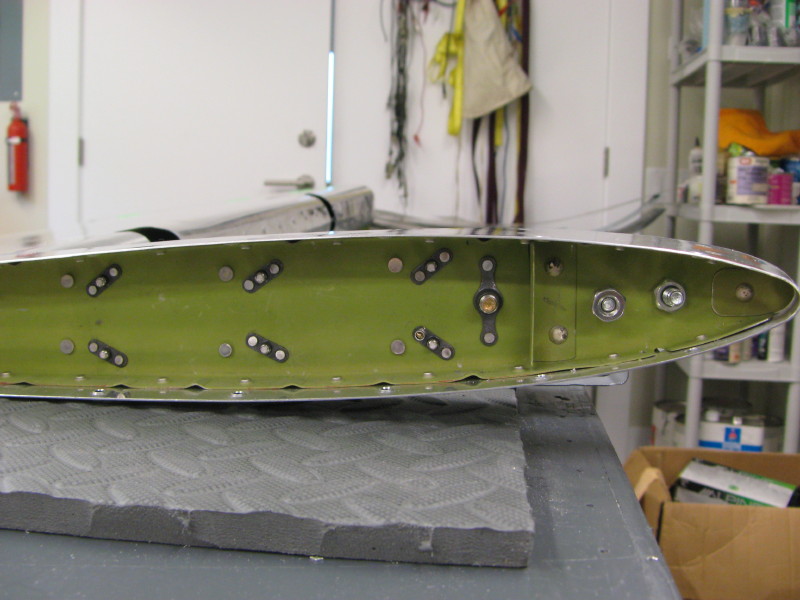
Final HS Stiffener Attachment
Stiffeners are Prosealed in place and attached with NAS1093AD3 rivets
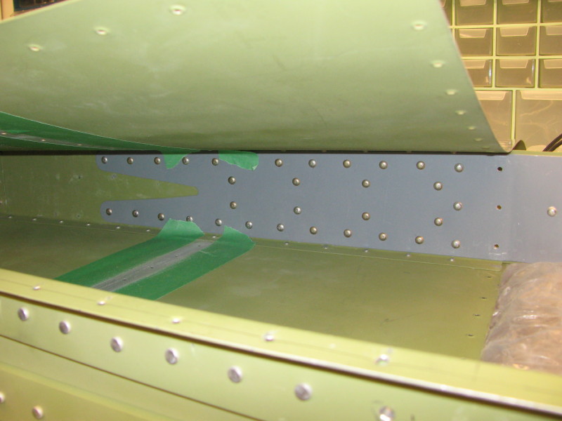
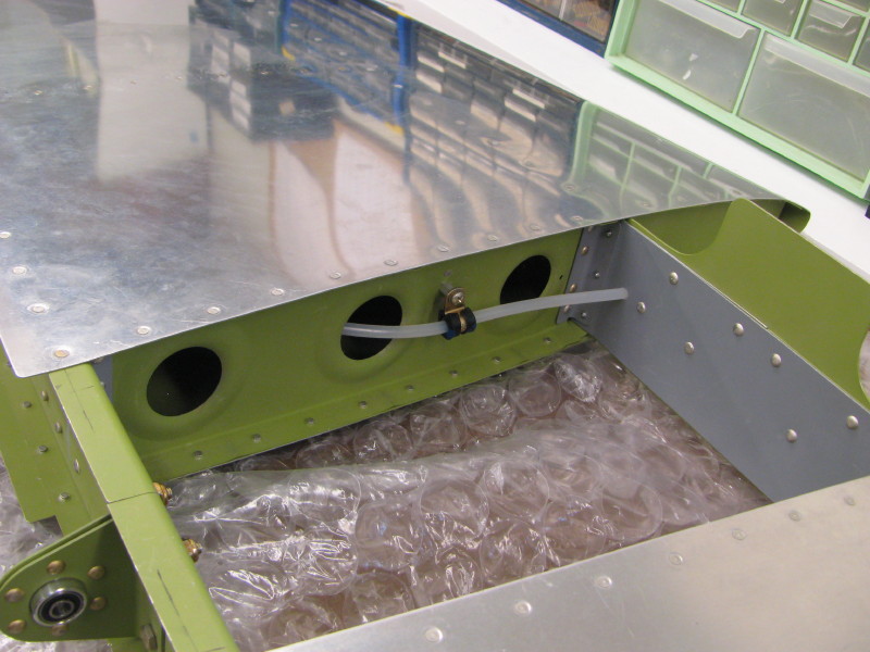
Reinforced HS Spar (center), with Rib flange modification and Elevator Trim conduit
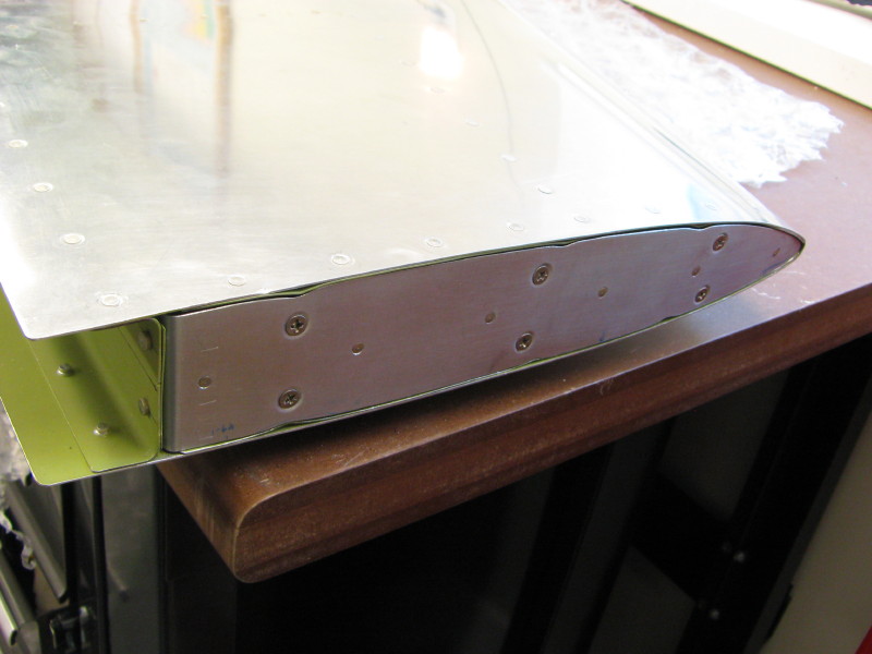
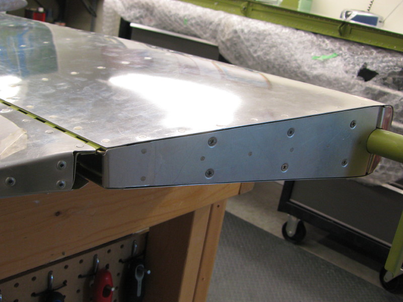
Control Surface End Plates
The HS and Elevator ends were covered with custom fit end plates made of 0.025 sheet stock, 6-32 standoffs and plate nuts. This is a lot of work, but the intention is to make them removable for simple speed comparisons with and without the end plates.
These are the finished plates for the elevator counterweight extensions. Careful fitting is required so the end plates do not sit proud of the skins and interfere with the proper operation of the elevators. Also, the plates are made a bit undersize to allow for paint.
NOTE: I have subsequently learned that the counterweight balance volumes need to be at least twice as large on both sides! This is due to the thicker skins and electrict trim servo (left side). It's easy to make the weight smaller, but hard to make it larger!
These photos show the standoffs and plate nuts used to attach them. The standoffs have a threaded male screw end that threads into the plate nut. Since the plate nut is steel and the standoff is aluminum, run a screw through the plate nut threads first to open them up and prevent galling of the aluminum.
The 1/4" bolt and washers are actually a point where counterweight mass can be adjusted by adding or deleting washers. This simplifies adjustments before and after painting or removing the end plates for flight testing.
The HS end plates need some extra thinking. I opened up a tooling hole to 1/4" to allow plate nuts to be threaded into position and used 3/32 Cherry blind rivets to hold them in place.
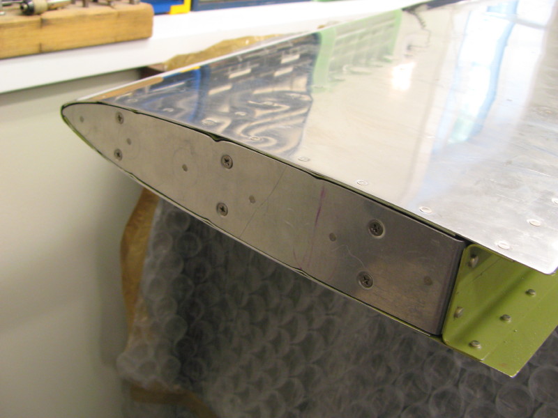
Here's the finished HS end plates.
The root end of the
elevators need a plate to seal off the end of the rolled leading edge.
These were Prosealed in place. Both the end plate and elevator
skins were roughened up to promote adhesion of the Proseal.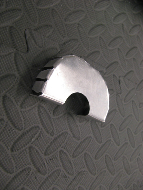
Elevator Root End Plates
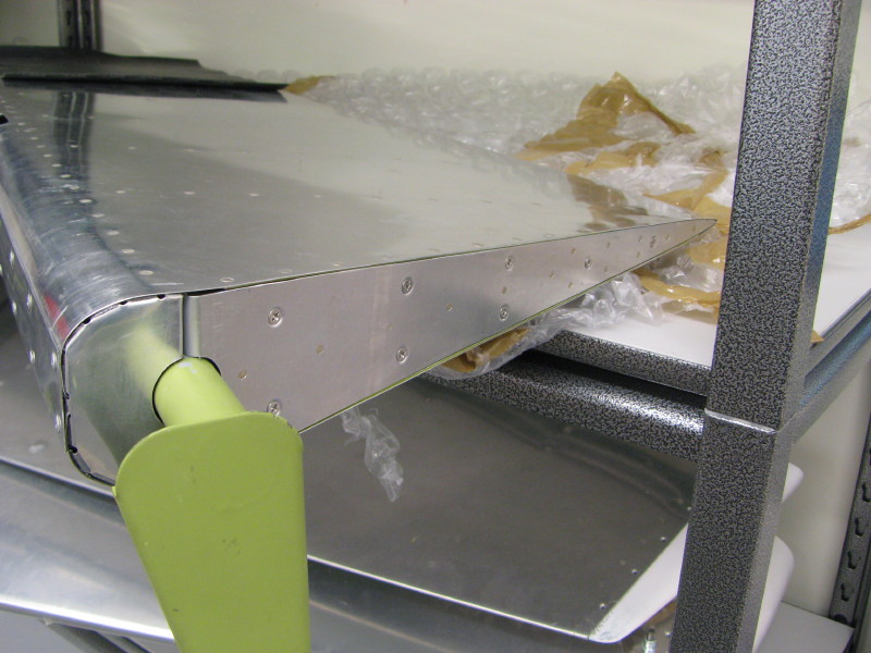
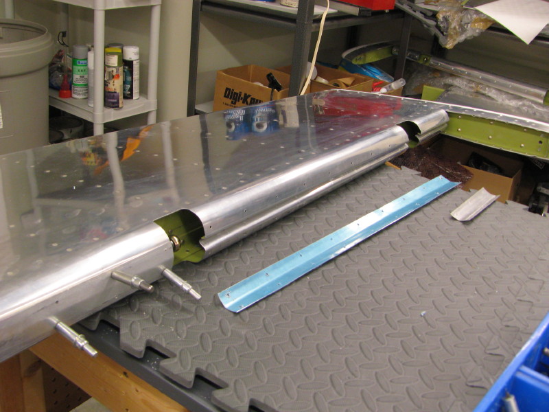
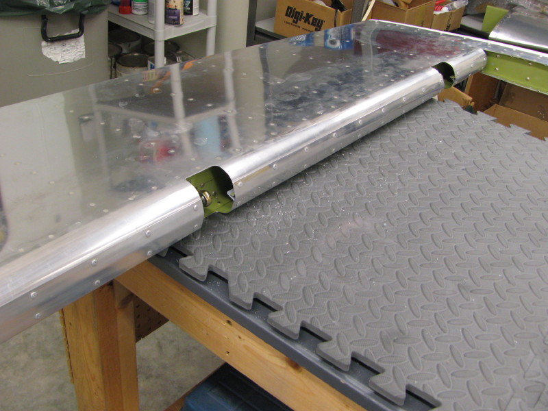
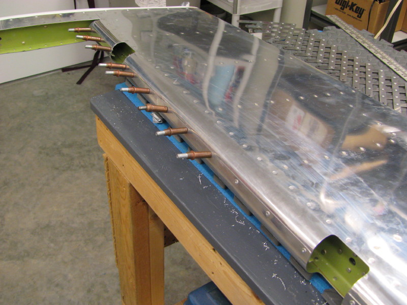
Rolling the Elevator Leading Edge
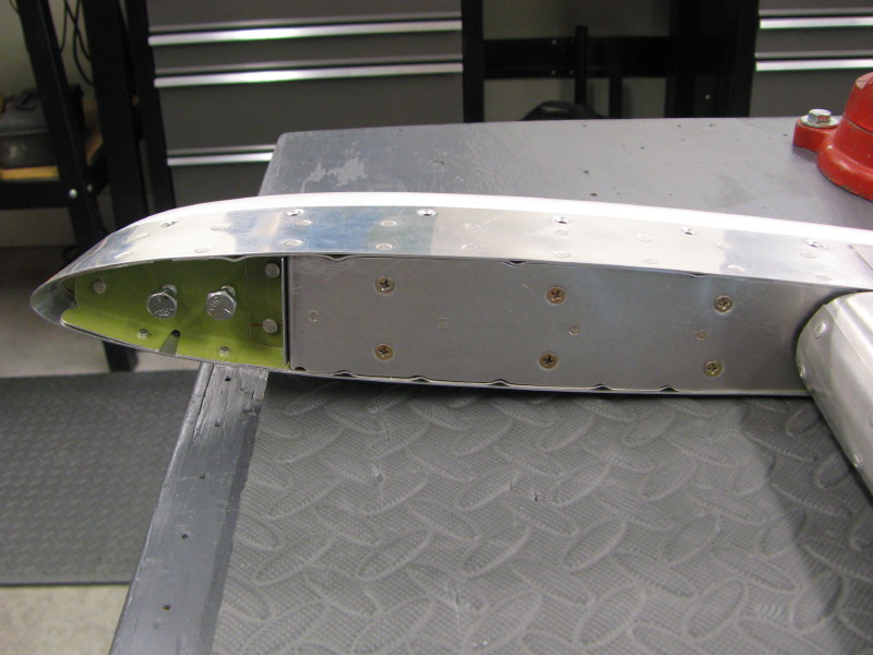
The Harmon Rocket instructions show the leading edges of the elevators rolled, but not riveted together. The RV-4 instructions show them rolled and riveted, with one skin having a flange and the other overlapping. Unfortunately, I did not notice that one elevator had both skins flanged (like a Rocket) and the other one did not (like and RV-4).
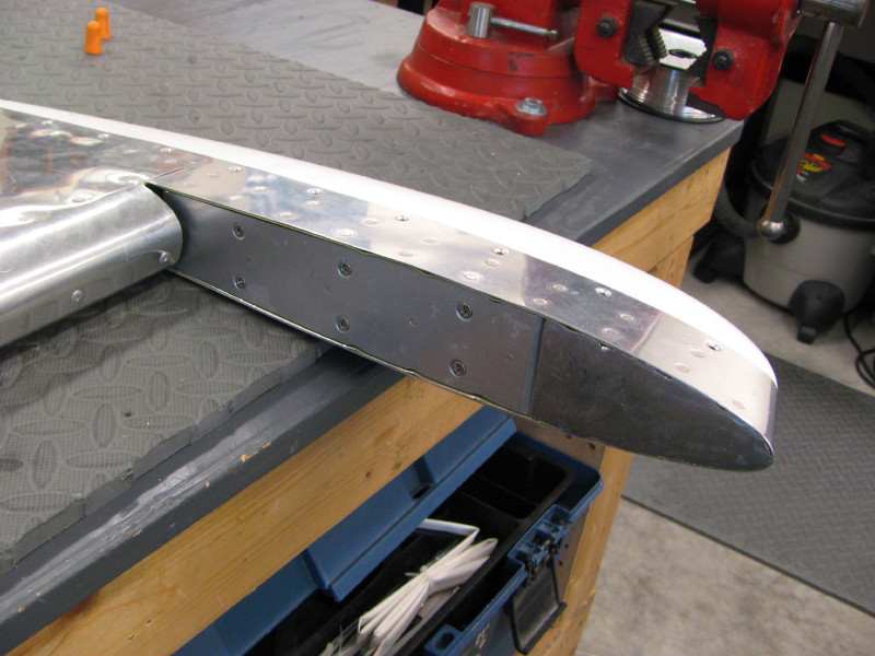
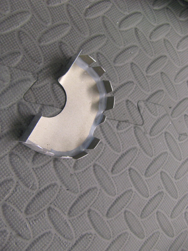
Therefore, I finished the leading edge of one like a Rocket, and the other like and RV-4 (riveted). I didn't like this, so I fabricated a splice plate for the Rocket leading edge and riveted it into place to make it more like the RV-4 design. I'm happy with the result.
The Rocket leading edge + a splice plate
The RV-4 leading edge (no splice plate):
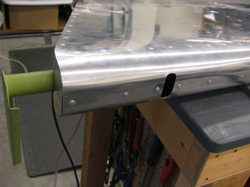
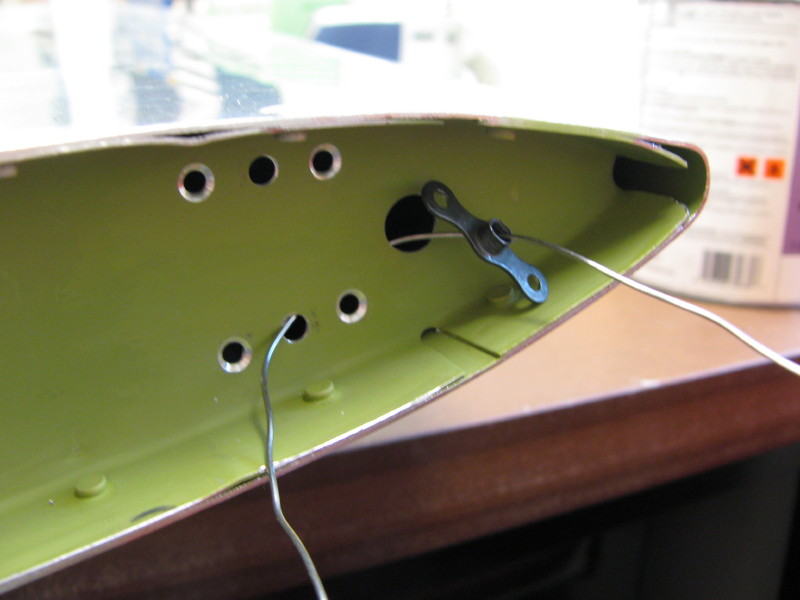
Elevator Trim Cable Opening
This opening is similar to the one used in my RV-9A for routing the manual trim cable. I will use this for routing the wires for the electric trim servo in the Rocket. The elevator spar is penetrated with a 1/4" hole with a snap bushing.