| Home | Empennage | Wings | Fuselage | Controls | Canopy | FWF | Panel |
|
|
Firewall Forward Last Update: October 17, 2012 |
| Home | Empennage | Wings | Fuselage | Controls | Canopy | FWF | Panel |
|
|
Firewall Forward Last Update: October 17, 2012 |
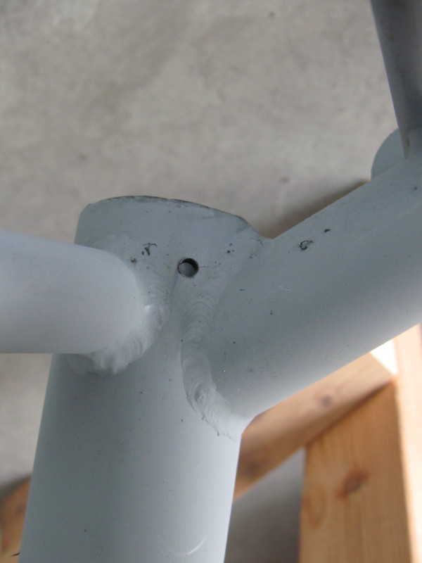
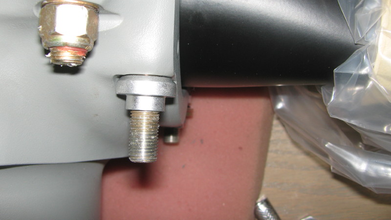
I reamed the main gear leg sockets using a brake hone to carefully open up the holes and remove and paint/corrosion/roughness. The result was an interference fit that required a fair amount of persuasion to insert the gear legs. The legs were rotated using a big crescent wrench on the gear leg flats (some tape will protect the legs). The flats need to be at 90 degrees to the horizontal with the engine mount levelled on the bench. The technique I used to level the mount was to carefully level it flat on a work bench, weighted down with lead, batteries, power tools and other massive objects.
Drilling: The titanium gear and engine mount need to be carefully match drilled for a AN5 or AN175 bolt. Once everything was trued up (level engine mount, 90 degree flats) and the legs fully inserted into the sockets, I carefully marked the position of the retaining bolt holes and drilled #30 through one side of the engine mount and about 1/8" into the titanium gear leg. Repeat for both legs, remove them and take them to a machine shop to drill and enlarge the holes to slightly undersize. In your shop, enlarge the holes on the engine mount using the same undersize drill, reinsert the gear leg and line-up carefully using a drift pin.
Once aligned, using the same undersize bit and plenty of lubricant, drill all the way through the backside of the engine mount (using a 1/2" electric drill-do not attempt this with a smaller drill motor or you may run out of torque). Finish up using the appropriate 5/16" undersize straight reamer. Your AN175 bolts should then fit with close tolerance.
In summary, the key to a good fit is to have the gear legs carefully drilled undersized. I used a machine shop, but a high quality drill press and careful alignment will allow you to DIY. The gear leg then becomes the guide to match drill the engine mount to the same undersize. Use a 1/2" electric drill for the final drilling to prevent chatter or work hardening the material. Finally, use a straight reamer to finish the holes to the required diameter. Saves expensive mistakes.

Engine Arrives. Purchased from Bart Lalonde at AeroSport Power.


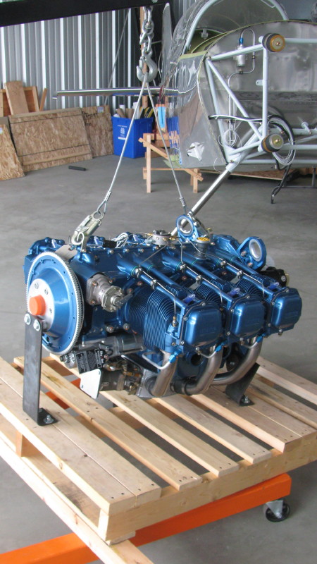
Originally, it was equipped with a Raven cold-air induction system and an RSA-10 servo. In order to fit the induction system, the stock sump had to be modified, which effectively destroys the possibility of going back to a stock induction.


The first problem was that the stock Rocket cowling would not fit. The alarm bells started ringing at this point.


Going back to a stock system will require the replacement of the modified sump.


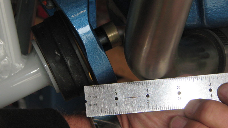
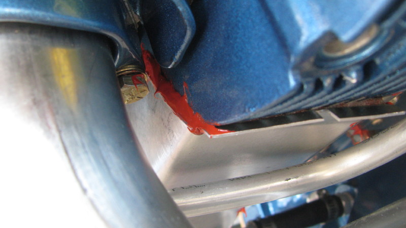
The Raven #3 induction tube interferes with the engine mount.
So, off came the induction system and sump.


The RSA-10 was swapped for an RSA-5 and a 95 degree elbow (more about this later).
Here's my second crack at the induction system. Injector elbow as supplied by AeroSport, and throttle-mixture standoff that I fabricated. Looks great, too bad I had to tear it all apart and re-do.

Unfortunately, the AeroSport elbow did not place the servo in the right position, so I purchased the Harmon supplied part, which does. It needs the forward studs to be removed and bolts used. The bolts are a very tight fit and are difficult to turn. Harmon's part is not a precision device.

With the elbow in place, the injector support bracket does not fit well. I'll try to loosen all the bolts and finagle it some more, Update, this worked.
Cowling Fit-Up
After trimming the cowling to fit the fuselage, reinforcements are required for the lateral hinges and aft Skybolt fasteners. Aft flange brings the cowl flush to the forward fuselage, and side flanges are built up to match the lower cowl thickness. Lower cowl is thicker because I cut off the joggle so that I can use hinges to attach the top and bottom cowls together.

Drilling the cowl hinges.

Spent some time sealing up air leaks on the inter-cylinder baffles.


I purchased an RV-10 plenum cover from RVBits. At least I knew if wouldn't fit when I ordered it. The RV-10 cowling is wider and flatter, while the Rocket is narrower and curves across the top much more. I thought that I could make it fit.
The first step was to trim the Van's baffles to about 3/8" clearance to the cowl. Ideally, this should be as close to the cowl as possible (1/4" would be better) to maximize plenum volume. I used paperclips to measure the clearance. Fitting the cowling in place then displaces the clips so clearance can be measured.

Here`s some pics of the as-built plenum cover.


The first step was to curve the plenum to fit the trimmed baffles. This required relief holes/slots to be cut around the edges as shown in the photos. A heat gun was used to soften the fiberglass and aid in bending. Tape was used to keep the curl while the fiberglass cooled. Later on, once everything fits well, these slots will be glassed in.


The next step was to cut the plenum down the middle. Because of the tight curve, it shortens the span and this cut is necessary to make it wider. An 0.40 aluminum splice plate was used to join the halves, and the interior had several layers of fiberglass bonded to it and the aluminum strip. After the glass set up, AN426-AD3 rivets were used to attach the strip.


There are places where the plenum doesn`t fit well. I mixed up a slurry of flox and cabosil to make a structural putty to fill the gaps. Rinse, lather, repeat as required.


Since the filler piece for the #6 cylinder that is provided with the RV-10 baffle kit does not fit, I fabricated an 0.032 aluminum filler piece and attached it the plenum cover with JB Weld and rivets. The plenum cover looks a lot like a Frankenstein's monster at this point, with cuts, splices and appendages riveted on.


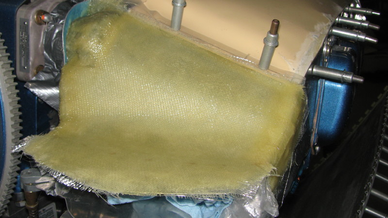
After trimming the baffles to fit the cowling closely, I fabricated the intake ramps. First I made cardboard cutouts, then I fabricated some thin soft aluminum pieces that matched. These were clecoed to the plenum cover and waxed. Several layers of fiberglass were then layed up over the ramp, rolling over the vertical sides to make flanges.

The photo below shows the fiberglass layup. The blue tint is from the plastic coating on the aluminum sheet that I left on. After everything set up, I removed the ramp and trimmed it to fit.

A little bit of microballoon slurry was used fill in the weave and pinholes.


The left scoop is a bit more complicated because of the prop governer. I taped up the governer and made a dam (blue aluminum sheet in the photo), and fabricated a thin aluminum sheet scoop mould onto which I did the fiberglass layup.


The finished product. The screws are temporary for checking the cowl baffle fit-up.

Here's how I sealed around the governor. The zip tie should hold it in place, but a piece of safety wire may be better.

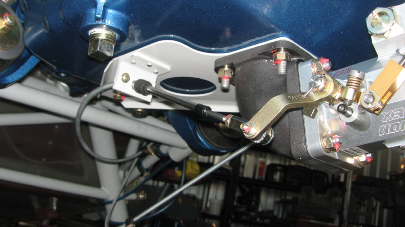
After much consideration, I decided to mount the oil cooler behind the #5 cylinder. There is plenty of room there, and it places the oil lines in a convenient spot for routing. The HRII engine mount has a hand hard point on the engine mount that is useful for mounting the cooler. I also fabricated a bracket that ties the aft part of the cooler onto the engine mount using cushion clamps. The cushion clamp in the top center will also be used to secure the cooler.


I cut a rectangular hole in the aft baffle. It was generally aligned with the cooler.

Using cardboard, I mocked up a duct and fabricated the pieces out of thin aluminum sheet. The 0.063 angle is used to attach to the cooler and provide structural integrity to the cooler mount. The duct is not perfectly symmetrical because the oil cooler and engine baffle are not perfectly aligned. That's what the rubber baffle strips are for.

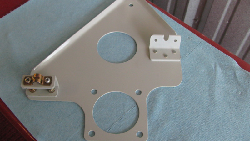
Brackets and rubber baffles were fabricated to provide a tight seal between the engine baffle plate and the duct. The apparatus on the bottom left of the picture below is the oil cooler air intake door. It mounts to the engine baffle plate and swings back to allow more air through the cooler. It is a piece of 0.032 with 1/2" flanges bent into the sides and a piece of 0.063 angle on the center line for Bowden cable to attach. I made it slightly under width to prevent binding. This all came together nicely, and It's easy to add the oil cooler door after everything else is fit.

The oil filler recess is a bit challenging, but ultimately rewarding. I did this because it provides a nice positive way to seal the filler neck and provide access for large hands. A side benefit is that it will allow for a hidden hinge to be used on the cowling door. Hidden hinges protrude inside an inch or two, so this box provides the necessary volume for this. A bending brake comes in handy here to form all the pieces. The bottom piece (top in the photo) is square and is roughly level, but not parallel to the engine.
The hole position is arbitrary. It's off to the corner here because the box matches the existing plenum cut-out, which is offset.

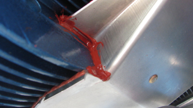
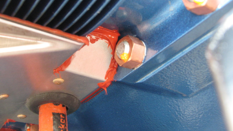
In order to follow the curve of the plenum cover, it's necessary to scallop the flange on the front and back sides as shown in the photos. The relief holes and slots will be filled with Proseal later on.
The seal around the engine's oil filler neck is a piece of rubber baffle material that has been feathered (many short radial cuts in the material) to allow it to flex around the filler neck and form a seal.

The baffle seal is held on with a retainer ring and four 4-40 screws. Using screws allows the baffle material to be easily replaced when necessary.


Propeller mushroom spacer designed for composite backplates. Unfortunately, someone at Hartzell goofed with this design because it requires the spinner backplates to be drilled out to 3/8", which leaves almost no edge distance around the holes.

Hartzell spinner cutout template:
photos\fwf\8068D_Van's-Hartzell_Cutout_Temp_.pdf
Spinner Disc
The cowling did not fit the spinner disc very well. It was skewed, plus the gap was a bit too large for my liking. This is typical of RVs and some surgery is required. Also, if I had the prop attached when I fit the cowl, I could have made this fit better right away. Instead, I used a plywood disc and spacers to simulate the spinner backplate- wrong choice.
I had some balsa left over from 1979 that was ideal for this. I used this to provid a build up that would help even the gap between the spinner and cowl. I bond the balsa to the cowling, and used some wood screws around the perimeter for additional security (not the ones pictured). Afterwards, everything was covered in fiberglass cloth and evened out with microballoons.
I closed down the disc to reduce the amount of air leakage behind the prop. I may install some kind of seal on this that rubs on the prop hub, but for now, it will be open.

The clearance around the hub is about a half inch. Later, the seal material may be installed to completely close this up. My calculations, however, show that this will reduce leakage from behind the spinner by 75%-- based on the unsealed area around the hub compared to the unsealed area behing the spinner.

