| Home | Empennage | Wings | Fuselage | Controls | Canopy | FWF | Panel |
|
|
Last Update: July 05, 2011 |
Wings As-Built

Fuel Fitting Service Bulletin:

Sealing the Access Plate
I inlaid dental floss around the circumference of the access panel, leaving the bitter ends exposed. The idea here is that if I ever have to remove the panel, I can pull on the floss and cut the seal easily. I hope that I never have to do this. The cork seals are not used in the Rocket, although I used them in my RV-9A.

Fuel drain.
I expect to add a moulded fairing later on.

I tried to seal the fuel filler cap for pressure testing. Took quite a bit of futzing to get right.

I sealed the fuel vent with a pinched off and RTV'd bit of tubing, and attached a balloon to the fuel pickup as shown. Then, using a blow gun attachment to my compressed air line, I filled the balloon through the fuel quick drain.

By marking on the balloon, I could determine if I had any leaks. This, coupled with soapy water sprayed on all of the rivets and fittings ensured there were no leaks.

Wing Alignment and Incidence
To set the sweep, I hung plumb bobs at the tips and roots of both wings. Beween the tips, I draped a line that hung down. When it just touches the wing root plumb lines, the wing sweep is set. The measurement between the same point on each wingtip to a reference point on the aft fuselage must also be identical when this is done. Then, the incidence is set using a digital level and the aft spar holes are drilled.
It helps to have the flaps fit to the wings before doing the drilling so that the flap skins can properly overlap the bottom fuselage skins. In my case, only the left flap skin fit well and I had to joggle the right one. Set the wing incidence prior to the tail incidence so that the flap overlap works and the critical edge distance on the aft spar holes is achieved. Then, match the incidence of the tail to the wings. This does not mean the same angle, just the same relative angles that the plans call out.


Wing Root Fairings.
I purchased the RV-6 wing root fairing material, although just a strip of 0.025 stock would have sufficed. Extensive trimming to get a good fitting strip was necessary, and some of the platenut positions will be underneath the rubber moulding. I chose this method over the fiberglass wing root fairing because it is cheaper, lighter and reduces drag.
To trace the outline of the fuselage, I used my edge marking tool. With the full width strip taped into position, but offset outboard from the fuselage, the edge marking tool is drawn along the fuselage to trace a trim line on the strip. The strip was bent to conform to the wing shape by moulding by hand on a 4" sewer pipe.


In order to use the RV-6 type of wing root fairing, the fuel tank attach brackets have to made differently than the RV-4 plans. The key to this is to ensure that the bracket does not interfere with the wing root fairing near the leading edge. This requires a 4-hole system with an internal doubler, shown in the pictures below. The shape of the external bracket is optimized to allow the inverted fuel line to pass underneath it.

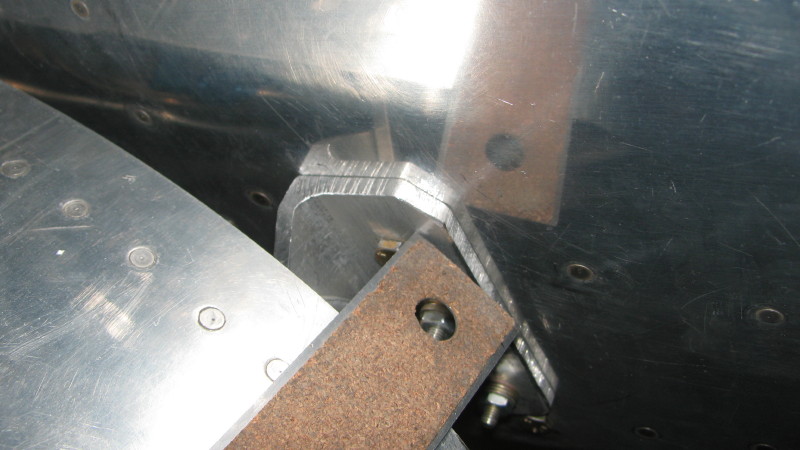
In order to fit flush with the fuselage, a 2-dimensional curve needs to be bent into the flange of the bracket. This is easy to do with a large vise and a crescent wrench, as shown below.

You can't see it in the photo, but this bracket has been bent to sit flush.

After a rough cut of the bracket, I used a stainless ruler to scratch the outline of the wing leading edge in the bracket, then trimmed it down to size.
The internal brackets are shown here, with a couple of keeper rivets to hold the assembly together.

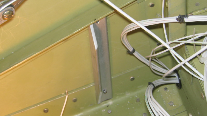
Here's how they look when mounted internally.
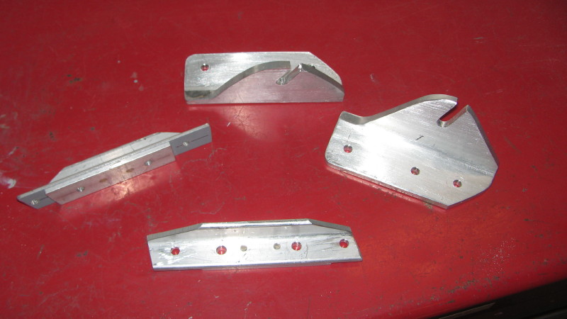
Here are the final brackets, with the internal doublers.
Here's some trimming I had to do on the left side fuel tank bracket. I'll smooth it out when the wing is pulled.

Flap Root Gap.
The flap root gaps were about 3/16", which is fine. However, I decided to add a metal fairing to close this gap (see below).

Flap Root Fairings.
These fairings are 3/4 x 3/4 0.032 angles, with MK-319-BS pull rivets. AN426 rivets are tough to drive on the inside of the angles, so the pull rivets seemed to be a good solution. The small fillet at the trailing edge was just for style.


Underneath, I trimmed the flap skin a bit too short, so I riveted on a tab to cover the push rod holes. Pretty simple on the left flap.

The right flap skin, however, needed to be joggled to provide a proper seal. I cut the flap skin, then fabricated a larger tab with a joggle and riveted it in place. This also covered the pushrod hole. The forward portion of the un-cut skin is also joggled, but it's tough to see in the photo. The combination of the bottom flap seal and the top flap fairing should clean up this area, reducing drag.

