|
Panel-Electrical Last Update: November 30, 2012 |
#Electrical_Systems_Architecture
#Breaker_Panel
#Instrument Panel

Electrical Systems Architecture
Since I'm an EE, I have a keen interest in the design of my aircraft electrical system. Having built an RV-9A, I gained considerable experience designing small aircraft electrical/avionics system. I was very happy with the result, but there are some things that I think I can do better this time around:
1. Use an internally regulated 60A (Plane Power) alternator rather
than the externally regulated 35A Honda alternator used previously. At
low rpm, normal loads can exceed the capability of the small alternator,
thus causing overheating and failure. This happened to me on a hot
day when performing pre-flight load testing.
2. Eliminate, as much as possible, load-carrying electrical switches.
I've had 3 switch failures in the RV-9A and even though I fixed this by
upgrading from Carling to Honeywell/MicroSwitch types, the Rocket will use power relays for
switching loads. I'll use miniature toggle switches for control,
and a 5-position rotary switches to control wing lights.
3. Minimize the weight of the wiring wherever prudent. Part of the
solution to this is (2), but things like LED Strobes help a lot!
Actually, a switch + a relay is about 1 oz heavier, but the saving in
wire weight makes this at least a zero-sum proposition.
Items 2 & 3 can be addressed by a new load management system that uses low-power switches controlling 40A automotive relays. The ultimate expression of this is the Vertical Power Systems boxes that use software and solid-state switching to provide sophisticated electrical system management for small aircraft. In my opinion, however, it's too costly for the benefits provided and may have some nasty failure scenarios. The simpler switch-relay design that I plan is simple, reliable and fault isolating. Any failures that do occur can also be repaired easily, by replacing a commonly available relay or switch.
I am locating the relays near to the main load distribution (master) bus and circuit breakers. This location is also a convenient point for distributing power throughout the aircraft. I won't have heavy gauge wiring running from the breaker panel to the instrument panel, then back to the loads through a couple of connectors. Instead, I will use 22-gauge wires from the panel and grip switches to control the relays. These wires are easy to connectorize to make a removable panel, and I only need a single wire per switched circuit.
In some cases, keeping the heavy load wiring shorter has allowed me to use small gauge wires, saving even more weight.
I'm also using some custom-designed solid state relay decks for controlling trim and flap motor. The advantage of these is primarily in the ease of making them variable speed for trim control and the total elimination of stuck relay contacts causing runaway trim or flaps. Not strictly necessary, but it was an interesting design project. Using commercially available trim controllers was an option, but my design is double the density/half the space and can drive the flap motors as well.
Another plan to lower weight is to use toggle switches instead of the big, heavy ACS magneto switch. I also will be adding a keylock switch to ground the magnetos. This is simply a security precaution with the side benefit of a positive indication that the mags are grounded when the key is sitting on the glare shield. I will be using the same type of keylock switch to control the source for my 12V aux power connector: either the Master bus or the Battery bus. A key lock is useful here because the Battery bus is always live and I only want access to it when charging the battery. At all other times, I want it to be switched power. The key lock prevents passengers from messing with the 'lectrics.
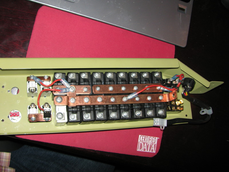
The breaker panel is mounted on the RHS of the pilot's seat. It provides the master bus and avionics bus breakers, plus the pair of breakers required for the Electroair ignition system. The two switches on the right are the Master Switch and the Avionics Switch. The two switches on the left (one missing) are for the magnetos/ignition system.
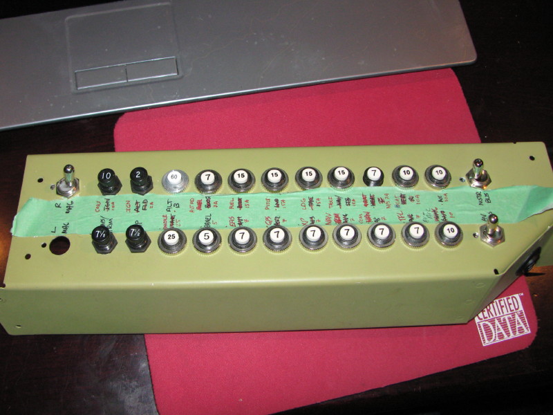
The ignition system has a separate hold-over essential bus battery, located in the tail. It will connect to the ignition bus with a 14AWG wire. The ignition bus is the pair of Klixon breakers on the left, connected with the copper strap. The device mounted to the ignition bus is a heavy-duty Schottky diode, used to isolate the ignition bus from the Master bus, yet provide charging current for the ignition battery and load current to the ignition system when the Master bus is energized. The V30100S diode is good for 30 amps, although the battery circuit has a 15A fuse located near the battery. In normal operation, the ignition system draws about 1 amp, although peak currents near 10A are expected. The diode was tested with a 4A forward current and it has less than 400mW of drop at this current. It did not even get warm to the touch, due to the large thermal mass of the copper strap and breakers. The V30100S uses the case as the cathode, simplifying installation. I connected both anodes of the dual diode device together to provide a more secure attachment for the soldered wire.
During engine cranking, the Master bus voltage can drop significantly, especially if the main battery is low or old. This can lead to backfiring and starter motor damage when using an electronic ignition. The purpose of the ignition hold-over battery is to isolate the ignition from these voltage drops. It also can run the ignition by itself for about 30 minutes if the Master bus is de-energized. Just enough time to get on the ground. Although I will be using a conventional magneto as a back-up, this 30 minute hold over is comforting. Finally, if the main battery should ever become discharged on the ground, the hold-over battery will allow the ignition system to be energized for hand-cranking. That should be fun with a high-compression IO-540.
The small red switch is typical of the miniature switches I am using throughout. These low-current switches control relays that switch the larger loads in the aircraft. They are quite a bit lighter and cheaper than the typical switches used, but they only have solder terminals. They come with a `standard-size` toggle and bushing, so they visually match a conventional toggle.

The bus bars are configured as a Master bus and an Avionics Bus. In the photo below, the Avionics bus feeds the 6 breakers at the top-right. The Avionics switch with the red wires connects the Avionics bus to the Master bus. The large white breaker is for the 60A alternator bus. The Master switch on the bottom right is a B&C 2-10 progressive transfer for OFF-BATT-ALT. The center position also enables the Starter. When switched to ALT, it disables the starter circuit to prevent accidental in-flight actuation from the stick-grip starter switch.
The circular black switch with the wire pigtail is the pilot's seat heat switch. The bent copper lug with the 0.25 inch hole is where the fat wire from the master contactor connects to the Master Bus.
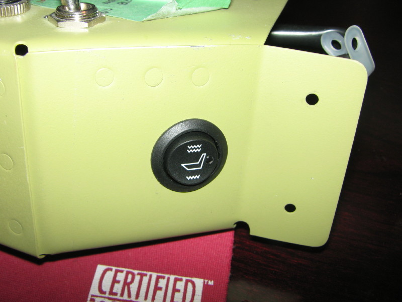
Here's a closer look at the pilot's seat heater switch. Three positions: OFF-WARM-HOT. There is also a Seat Heat Master Switch on the panel. This allows complete pilot control of seat heat power for both the front and back seats. My opinion is that the pilot should be able to disable any back-seat electrical loads during an emergency. This also applies to the rear-seat auxiliary power jack.
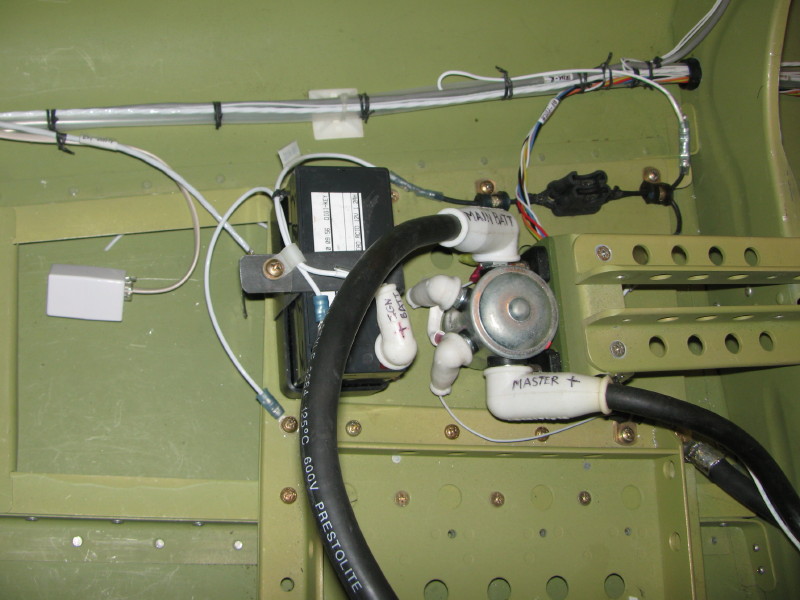
I made a design modification by adding an ignition hold-over battery for the Electroair ignition. This system uses a small 1.2 AH AGM battery, mounted near the main battery. The mounting location is primarily for weight and balance purposes, plus there was an appropriate location.
The battery tray is actually a plastic electronics enclosure box that fit the battery perfectly. It is mounted to the structure with screws and an aluminum doubler plate for stiffness. The box has small bumps on the bottom that support it a bit proud of the structure, allowing the steel strap to go underneath and wrap around the battery. Notice the two fuse blocks: one for the auxiliary power jack which can be used for main battery charging; and the second for the ignition hold-over battery circuit. White insulating boots protect all of the positive terminals from accidental shorts (dropped wrenches).
Also visible is the pre-wire for the ELT (telephone cable and a shielded wire for the RS-232 data and power just visible underneath the battery hold-down strap).
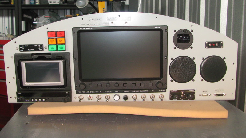
Here's the final version of my panel. I eliminated IFR capability because it's overkill for my mission. This is a stock HR-II panel blank, with the ends cut as shown. The main panel is tilted 8 degrees up to improve sight lines. The Fuselage page shows how I did this.
The Trutrak Gemini PFD is optional. In fact, the IFR upgrade plan is to swap out the Aera with a certified GPS (Garmin 430 or 650), install the second EFIS and plug an SL-30 into the radio tray (initially will be an SL-40 in an SL-30 tray). I originally planned a second SkyView system in my panel, but all it added was redundancy, with no new capabilities-but at a significant cost. The Trutrak offers flight instrument redundancy at a modest cost, and does not consume a lot of panel area. If Garmin ever offers a 3" SkyView with built-in gyros, my plans may change. The D6/D10A is too deep to fit my panel in this location.
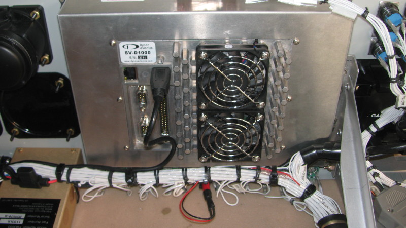
The iPhone is using a RAM mount and is optional. Below the iPhone is the Dynon USB connector, plus a 15-pin DSub connector that provides a number of audio connections (music input, pilot mic output) and a serial port to the SkyView D1000. With this port, I can hardwire a cell-phone or music player into my audio system. This is useful for non-bluetooth headsets, such as a flight helmet or a DC.
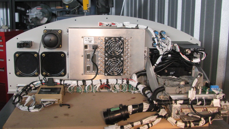
Complete Panel
The complete panel matches the planned panel in almost all details. Some of the annunciator details have changed, and the Trutrak EFIS and iPHONE are not installed. Panel was powdercoated at a local shop. Note that the Garmin Aera supports MP3 playback. I have tested this on the bench and it works well. On the panel, however, the PS Engineering intercom limits the audio quality (as does the headset). If this becomes an issue, I will install one of my Vx Aviation ASX-2A (or 2B) devices which provide true hi-fi stereo sound and use a Bose or Lightspeed headset.
Details of the panel wiring shown below is the single-point audio ground I used by removing a case screw from the PS Engineering intercom.
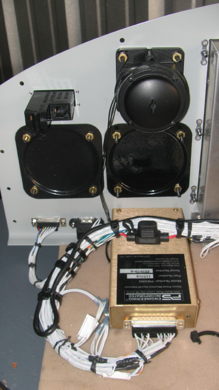
The red and black contraption below the SkyView screen is the LED used for the switch legend strip backlight. Although it's a white LED, the red shroud casts a nice dim red light into the pilot's footwell and fuel selector... nice.
I used some Vx Aviation products to complete the details of the avionics. I used the AMX-2A 10-channel audio mixer, and prototype versions of the IL-6A 6-channel annunciator controller and the WWX-1A wig-wag controller.
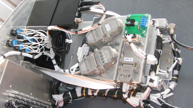
Putting it all together, you can see the 63 pin circular panel connector (CPC-Series 2) for signals and two Universal Mate-N-Lok (UML) power connectors for powers and grounds.
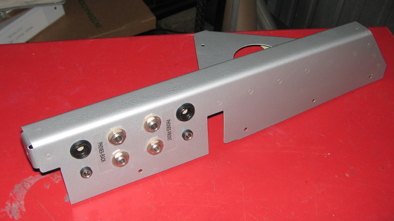
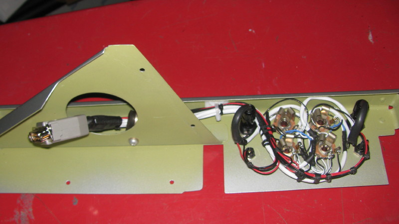
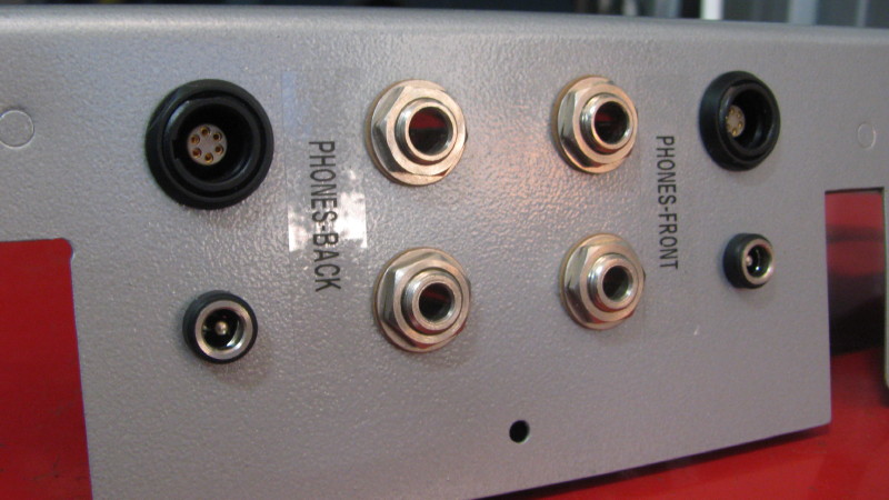
The jack panel consists of pilot and copilot aviation jacks, 10 volt regulated power and Bose-Lightspeed Lemo jacks. Not shown is that this panel also holds the fire extiguisher on the blank surface.